
Home → Applications → Self-supporting tunnel lining membranes
Self-supporting tunnel lining membranes
Self-supporting tunnel lining membranes require a continuous barrier matched to water exposure, substrate movement and maintenance. This engineering guide frames the application intent without replacing the current system specification or product technical data sheet.

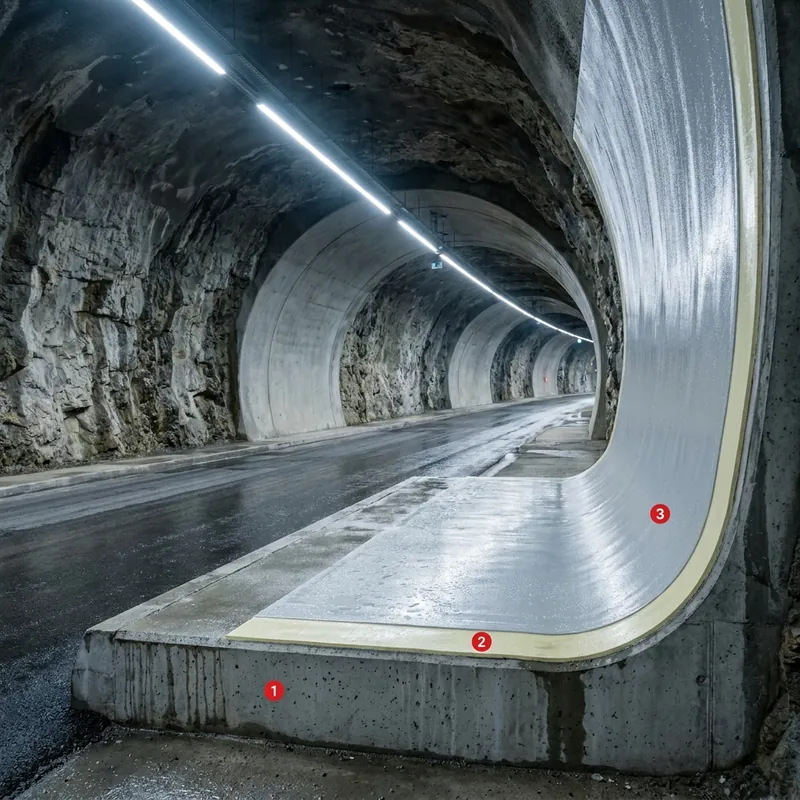
Use and application
The application intent is self-supporting tunnel lining membranes. Start by qualifying the substrate, exposure, service level and maintenance constraints. Compare the current Products and Systems documentation.
01
Self-support, pressure and membrane detailing
A self-supporting tunnel lining membrane is a structural and waterproofing interface, not simply a thicker coating. Define the pressure case, substrate movement, anchorage or detailing, and inspection method before selecting a build-up.
02
Layers and references
Define the sequence from prepared substrate through primer or bond coat, functional membrane or body coat, reinforcement where specified, and protective or finish layer where required. Use the current technical data sheet for preparation, mixing, consumption, thickness, overcoat windows and cure; the Calculator supports quantities, while Systems and the product references establish the applicable route.
03
Common mistakes
- Treating the open field as the whole waterproofing detail and omitting joints, penetrations, corners or terminations.
- Applying over damp, contaminated or weak substrate without a documented preparation and moisture check.
- Selecting a product from the water label alone without checking chemistry, immersion, cleaning and repair requirements.
04
Operating sequence
1. Record the exposure, dimensions, substrate condition and service scenario. 2. Map joints, edges, penetrations, drains, upstands and repair zones. 3. Select a compatible route in Systems and verify every layer against the current technical data sheet. 4. Calculate quantities with the Calculator. 5. Approve a representative area, document preparation and application controls, inspect the completed build-up, and release it only when the project requirements are met.