
Home → Applications → Industrial resin floor systems
Industrial resin floor systems
Industrial resin floor systems must be specified for real traffic, cleaning, safety and substrate conditions. This engineering guide separates the use case from the visible finish and points to the checks required before installation.

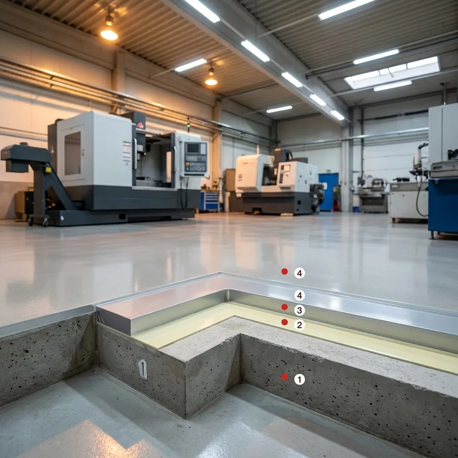
Use and application
This page covers industrial resin floor systems. Start by qualifying the substrate, exposure, service level and maintenance constraints. Porosity Sealer, Pavifloor and Colodur Eco are reference points for this use case, not an automatic system selection. Compare the current Products and Systems documentation, and use the associated application context at Industrial flooring to keep the scope distinct.
01
Traffic, safety and service conditions
Floor performance follows the actual traffic, impact, cleaning, slip and chemical exposure. Moisture and cohesion of the substrate, joints, falls, thresholds and transitions should be resolved before choosing the visible finish.
02
Layers and references
Define the sequence from prepared substrate through primer or bond coat, functional membrane or body coat, reinforcement where specified, and protective or finish layer where required. Use the current technical data sheet for preparation, mixing, consumption, thickness, overcoat windows and cure; the Calculator supports quantities, while Systems and the product references establish the applicable route.
03
Common mistakes
- Choosing a decorative or pedestrian finish for traffic, turning, impact or chemical loads it was not designed to carry.
- Coating damp, laitance-contaminated or weak concrete without diagnosis and suitable preparation.
- Leaving joints, coves, thresholds, drains and transitions out of the quantity take-off and inspection plan.
04
Operating sequence
1. Record the exposure, dimensions, substrate condition and service scenario. 2. Map joints, edges, penetrations, drains, upstands and repair zones. 3. Select a compatible route in Systems and verify every layer against the current technical data sheet. 4. Calculate quantities with the Calculator. 5. Approve a representative area, document preparation and application controls, inspect the completed build-up, and release it only when the project requirements are met.