
Home → Applications → Watering troughs
Watering troughs
Watering troughs require a continuous lining matched to livestock water immersion, trough geometry, cleaning regimes and agricultural exposure. This engineering guide frames the application intent without replacing the current system specification or product technical data sheet.
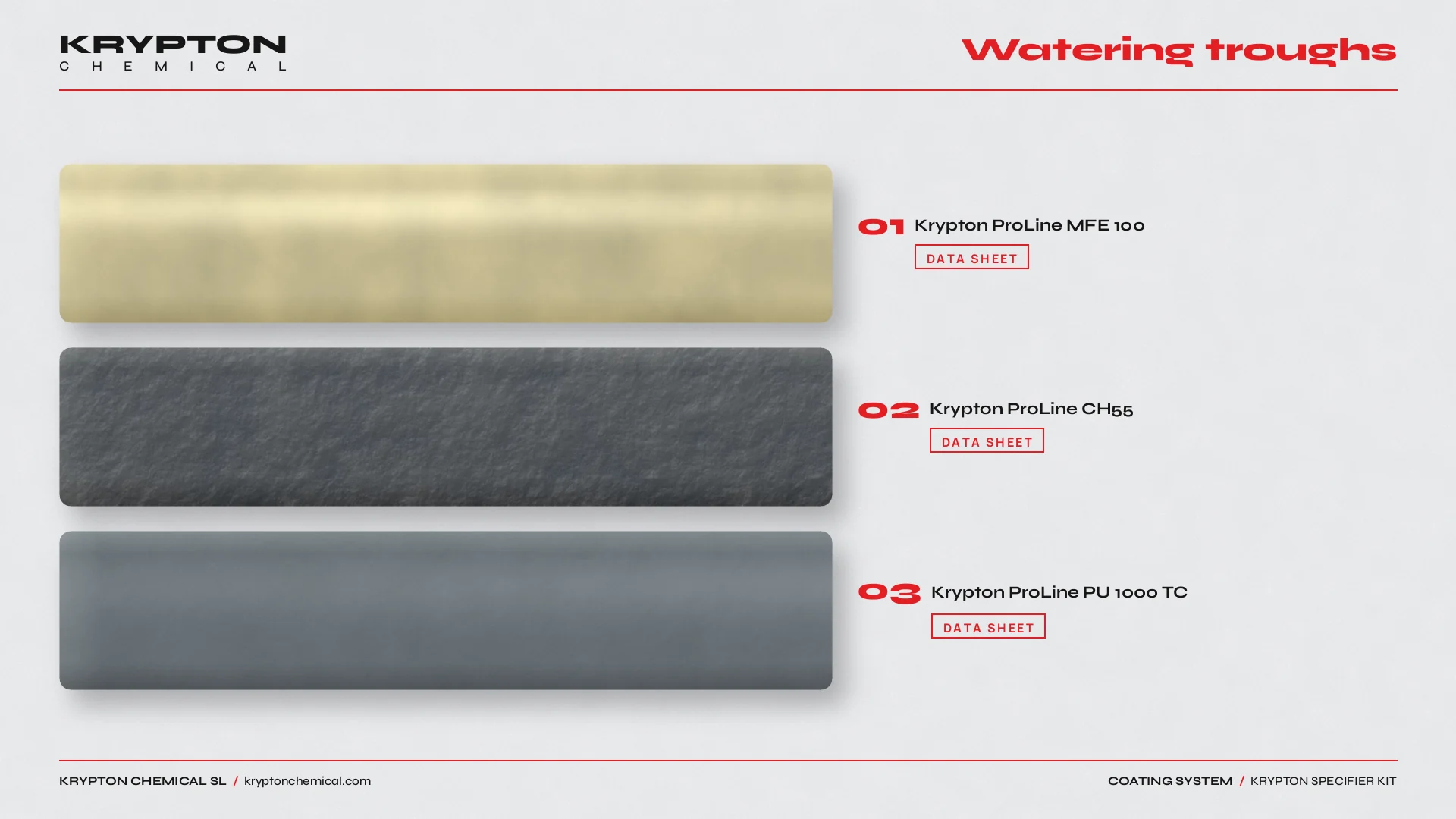 DATA SHEET · Krypton ProLine MFE 100
DATA SHEET · Krypton ProLine CH55
DATA SHEET · Krypton ProLine PU 1000 TC
Use and application
The application intent is waterproofing of watering troughs. Start by qualifying the substrate, exposure, service level and maintenance constraints. Krypton ProLine MFE 100, Krypton ProLine CH55 and Krypton ProLine PU 1000 TC are typical reference products for this application. Compare the current Products and Systems documentation, and use the associated application context at Livestock sheds to keep the scope distinct.
01
Immersion service and trough detailing
Troughs see continuous or intermittent water immersion, livestock contact, cleaning chemicals and outdoor UV where exposed. Concrete or rendered troughs bring porosity and cracking risk. Floors, walls, ends, overflow edges, pipe inlets and repair patches need a continuous, documented detail before the lining route is fixed.
02
Layers and references
Define the sequence from prepared substrate through primer or bond coat, functional membrane or body coat, reinforcement where specified, and protective or finish layer where required. Use the current technical data sheet for preparation, mixing, consumption, thickness, overcoat windows and cure; the Calculator supports quantities, while Systems and the product references establish the applicable route.
03
Common mistakes
- Selecting a lining from a generic waterproofing label without checking immersion, cleaning agents and livestock contact requirements.
- Omitting ends, overflow edges, pipe inlets and wall–floor junctions from the lining detail.
- Closing the build-up before checking adhesion, thickness, pinholes and cure under immersion conditions.
04
Operating sequence
1. Record water chemistry, cleaning regime, trough dimensions, substrate condition and service scenario. 2. Map junctions, overflows, pipe inlets and repair zones. 3. Select a compatible route in Systems and verify every layer against the current technical data sheet. 4. Calculate quantities with the Calculator. 5. Approve a representative area, document preparation and application controls, inspect continuity and release the trough only when the project requirements are met.