Home → Applications → Purification plants
Purification plants
Purification plants require continuous waterproofing and chemical-resistant linings matched to WWTP process structures, wastewater chemistry, immersion and plant maintenance regimes. This engineering guide frames the application intent without replacing the current system specification or product technical data sheet.
Use and application
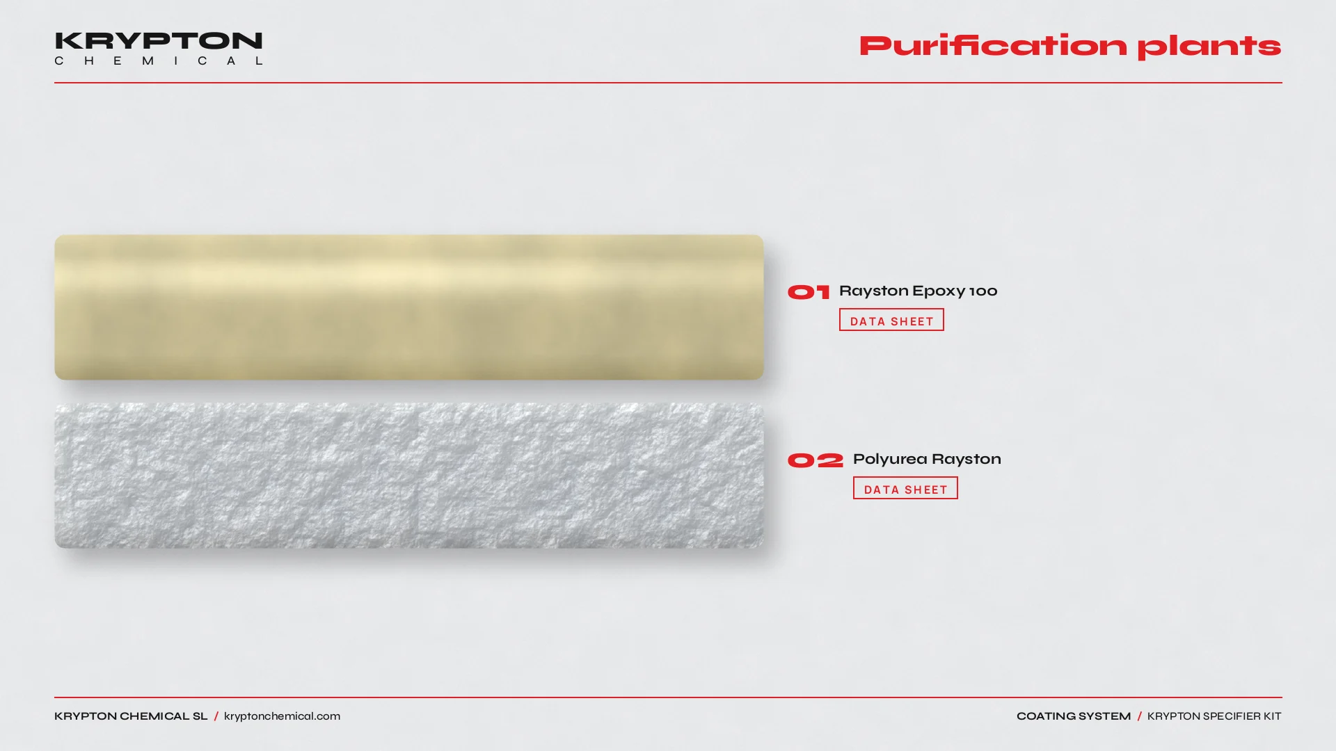
The application intent is waterproofing of purification plants. Start by qualifying the substrate, exposure, service level and maintenance constraints. Rayston Epoxy 100 and Polyurea Rayston are typical reference products for this application. Compare the current Products and Systems documentation, and use the associated application context at Digesters wwtps to keep the scope distinct.
01
Process structures, wastewater and immersion
WWTP process tanks, channels and chambers see wastewater, treatment chemicals, splash and vapour spaces that attack concrete. Exposure differs between primary, secondary and sludge zones. Joints, wall–floor transitions, weirs, penetrations, equipment mounts and inspection points need a continuous, documented detail before the lining route is fixed.
02
Layers and references
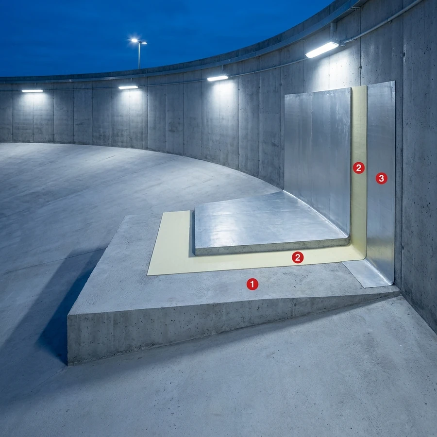
Define the sequence from prepared substrate through primer or bond coat, functional membrane or body coat, reinforcement where specified, and protective or finish layer where required. Use the current technical data sheet for preparation, mixing, consumption, thickness, overcoat windows and cure; the Calculator supports quantities, while Systems and the product references establish the applicable route.
03
Common mistakes
- Applying one lining specification across dissimilar process zones without checking chemistry, temperature and immersion duty.
- Omitting joints, weirs, penetrations, equipment mounts and wall–floor transitions from the lining detail.
- Closing the build-up before checking moisture, adhesion, thickness, pinholes and cure under process immersion conditions.
04
Operating sequence
1. Record process chemistry, immersion and vapour zones, structure dimensions, substrate condition and service scenario. 2. Map joints, transitions, weirs, penetrations, equipment mounts and repair areas. 3. Select a compatible route in Systems and verify every layer against the current technical data sheet. 4. Calculate quantities with the Calculator. 5. Approve a representative area, document preparation and application controls, inspect continuity and release the structure only when the project requirements are met.