
Home → Applications → Anti-corrosion pipe coatings
Anti-corrosion pipe coatings
Anti-corrosion pipe coatings require a continuous barrier matched to water exposure, substrate movement and maintenance. Match the build-up to substrate, exposure and detailing; confirm the current system specification and product technical data sheet.
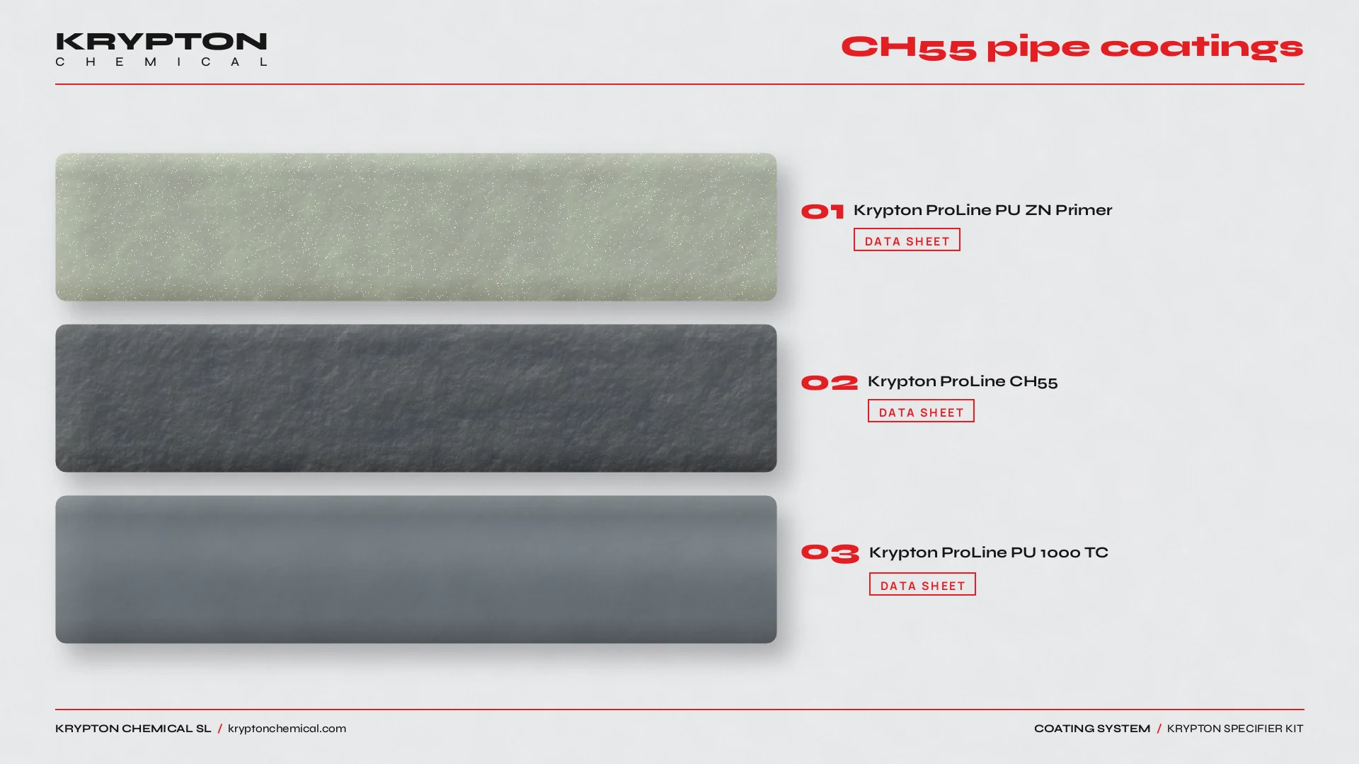 DATA SHEET · Krypton ProLine PU ZN Primer
DATA SHEET · Krypton ProLine CH55
DATA SHEET · Krypton ProLine PU 1000 TC
Use and application
This page covers anti-corrosion pipe coatings. Start by qualifying the substrate, exposure, service level and maintenance constraints. Krypton ProLine PU ZN Primer, Krypton ProLine CH55 and Krypton ProLine PU 1000 TC are reference points for this use case, not an automatic system selection. Compare the current Products and Systems documentation, and use the associated application context at Pipe linings to keep the scope distinct.
01
Water exposure, substrate movement and detailing
Anti-corrosion performance depends on surface preparation, corrosion category, wet/dry cycles, DFT continuity and maintenance access. Joints, corners, penetrations, thresholds and transitions need the same continuity as the main field.
02
Layers and references
Define the sequence from prepared substrate through primer or bond coat, functional membrane or body coat, reinforcement where specified, and protective or finish layer where required. Use the current technical data sheet for preparation, mixing, consumption, thickness, overcoat windows and cure; the Calculator supports quantities, while Systems and the product references establish the applicable route.
03
Common mistakes
- Treat continuous pipe runs as the whole coating scope and omit welds, flanges, supports, bends or repair zones.
- Applying over damp, contaminated or weak substrate without a documented preparation and moisture check.
- Selecting a product from a single corrosion class alone without checking surface prep, DFT, chemistry and repair requirements.
04
Operating sequence
1. Record the exposure, dimensions, substrate condition and service scenario. 2. Map joints, edges, penetrations, drains, upstands and repair zones. 3. Select a compatible route in Systems and verify every layer against the current technical data sheet. 4. Calculate quantities with the Calculator. 5. Approve a representative area, document preparation and application controls, inspect the completed build-up, and release it only when the project requirements are met.